

CASSSC Specification
This content is for the 1.0 version.
Minimum specification
Section titled “Minimum specification”| Property | Specification |
|---|---|
| Enclosed dimensions | 9 x 4.5 x 4.5 metres |
| External dimensions | 9.22 x 4.72 x 4.72 metres |
| Maximum contained mass | 60 tonnes (uniformly distributed across loaded side face) |
| Total empty mass | 10 tonnes |
| Stacking load | 13 CASSSC stack under Earth gravity, with load passing through corner posts of CASSSCs |
| Materials | Aluminium or steel alloy |
| Pressurisation | Pressurised CASSSCs must contain a 1 bar pressure whilst full and exposed to vacuum |
| Minimum safety factor | 2.0 |
Example CASSSC structure
Section titled “Example CASSSC structure”The standard structure of a CASSSC can be seen in Figures 1 and 2 below. The structure consists of a welded framework of aluminium or steel beams and cross members, with orthogrid sidewalls. Gaskets are used for sealing of pressurised containers. Sidewalls are joined to the frame using a combination of fasteners and/or welding techniques, depending on the manufacturer.
Part dimensions (Corten steel)
Section titled “Part dimensions (Corten steel)”| Part | Dimensions |
|---|---|
| Top side rail, bottom side rail | 100 x 100 x 15 mm box section, 9100 mm length |
| Top end rail, bottom end rail, door header, door sill | 80 x 80 x 12 mm box section, 4600 mm length |
| Corner post | 110 mm square bar, 4500 mm |
| Cross member | Not utilised for modern CASSSC designs due to integration with sidewall panel orthogrid structure. Older designs used 80 x 35 x 10 mm pieces spaced 1000 mm apart (skipping location with forklift pockets) |
| Forklift pockets | 400 x 150 x 20 mm C-shaped section, 4500 mm, located centrally along each sidewall, 3000 mm apart |
| Corner fitting | 200 mm box, with appropriate cut outs. Additional reinforcement at joints with side and end rails |
| Sidewall panel, endwall panel, roof panel, floor panels, door panels | Single orthogrid panels, 50 mm peak thickness, pockets of 45 mm depth and 360 x 450 mm length with 48 mm separation, additional cutouts to fit around cross members as necessary |
| Hinges | Stamped 10 mm pieces |
| Door locking bars | 30 mm rod with cast end attachments for locking |
All part dimensions are nominal, but reasonable manufacturing tolerances are acceptable. The figures below show the key structural elements of the CASSSC.
Figures
Section titled “Figures”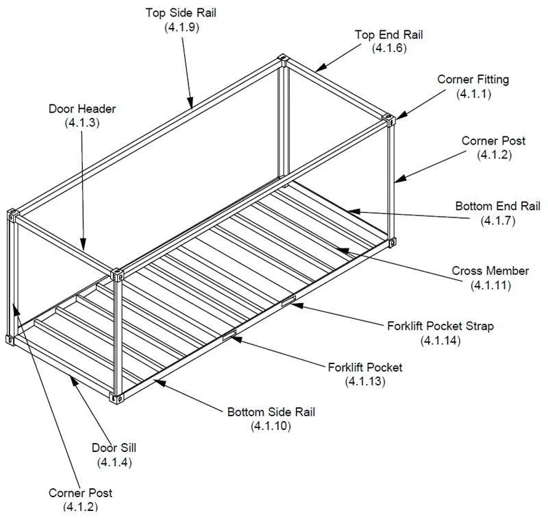
Figure 1: Main framework of the CASSSC. Image credit: Shipping and Freight Resource, 2022, Anatomy of a Shipping Container.
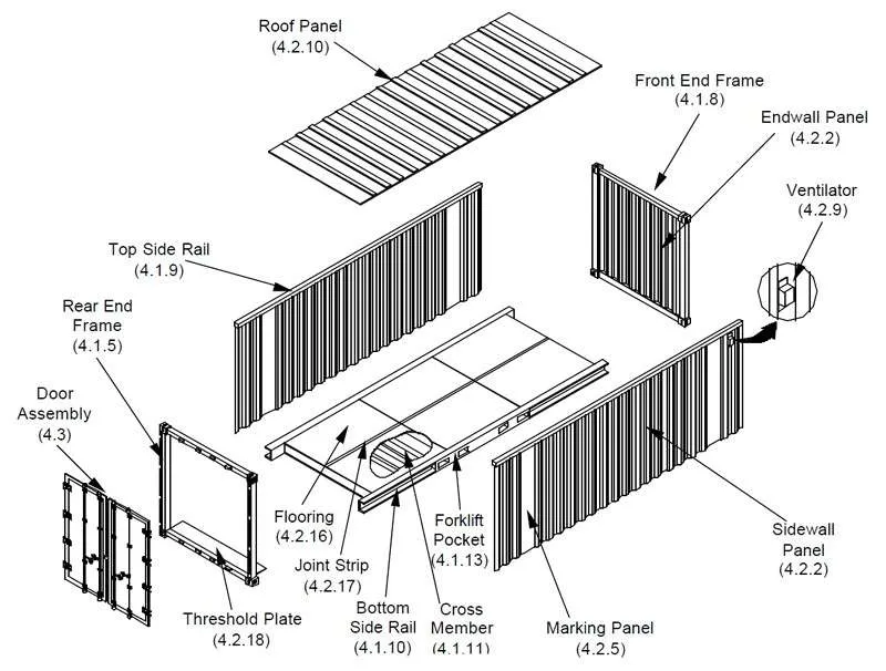
Figure 2: Exterior components of the CASSSC. Image credit: Shipping and Freight Resource, 2022, Anatomy of a Shipping Container.
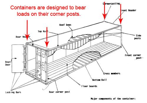
Figure 3: Stacking load diagram for a CASSSC in transport or storage. Image credit: Containers40, 2015, Container Technical Sheet.